[Omron Products] How to choose high-capacity relays for inrush current…
- 작성자 : 최고관리자
- 등록일 : 23-10-20 08:19
- 조회수 : 228회
본문
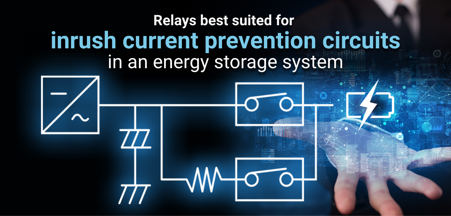
With pressing concerns about climate change and the need to reduce greenhouse gas emissions, there is growing interest in solar power generation as a clean method of power generation that emits less carbon dioxide than fossil fuels. However, power generation from renewable energy sources is affected weather conditions and seasonal variations, making it difficult to ensure a stable supply of electricity. Since storage batteries can store generated electricity, they can stabilize the electricity supply even when power generation is unstable or when demand for electricity is high. Energy storage systems (ESS) use a direct current power source, so a direct current circuit is used for charging and discharging circuits. Safety control in direct current circuits is becoming increasingly important for energy storage systems with increasingly higher voltages. In these systems, an inrush current prevention circuit (precharge circuit), which suppresses the inrush current that occurs at the moment power is turned on, and a discharge circuit, which quickly discharges the electricity remaining in the device to ensure safety during use, play an important role.
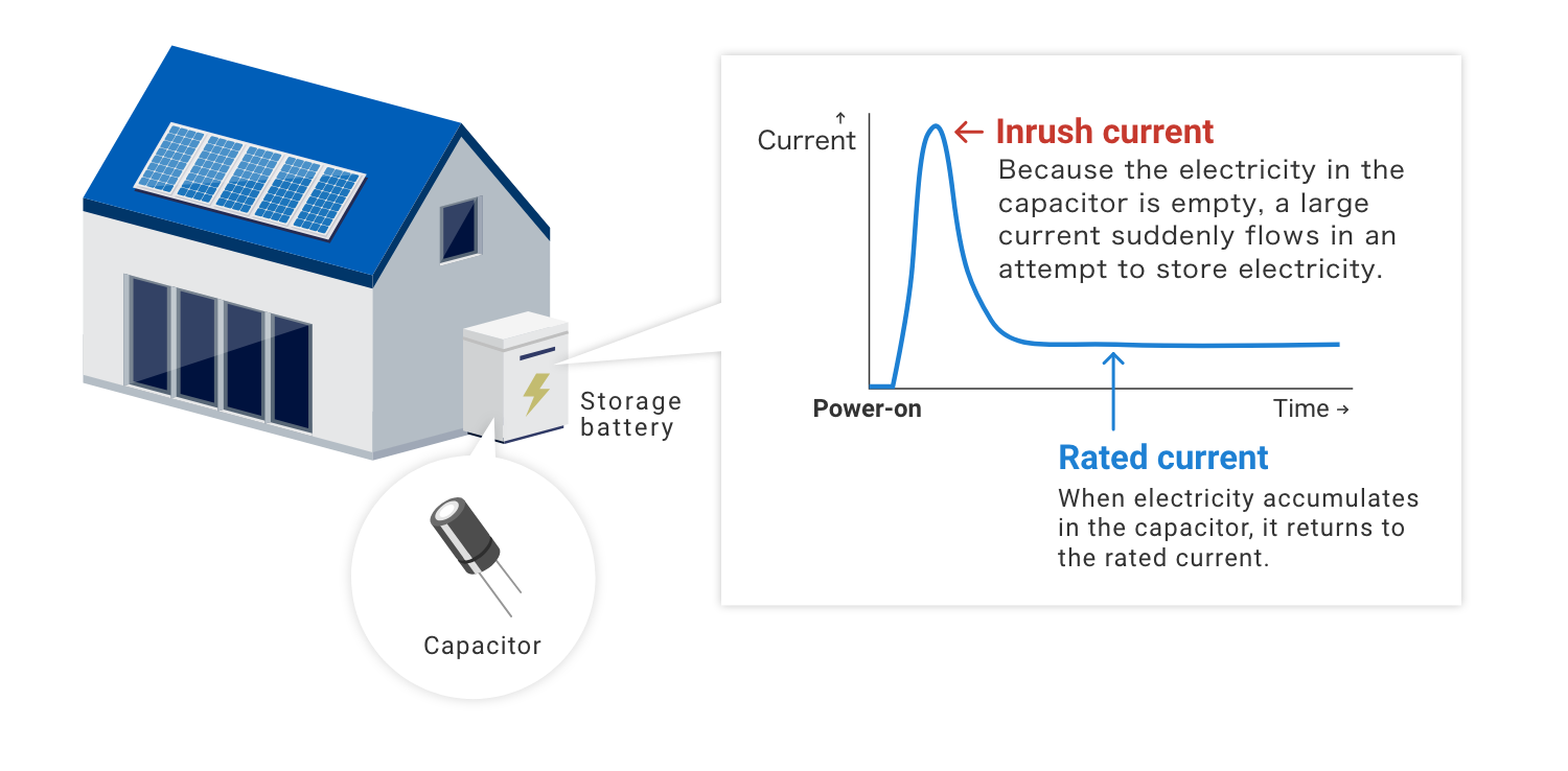
What is inrush current?
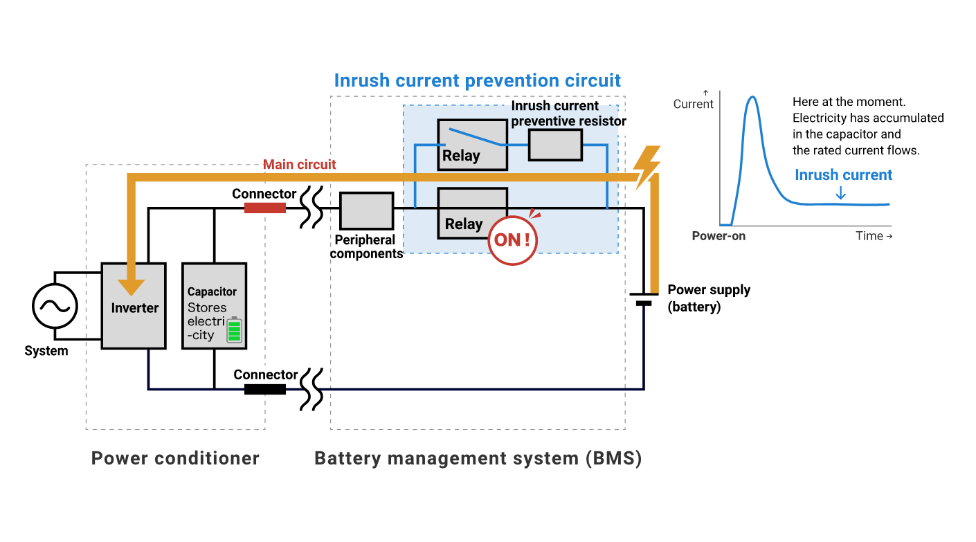
Inrush current is a current much larger than the steady-state current that flows at the moment power is applied to a device. In an inverter circuit, etc., a capacitor is first charged with electricity when power is turned on, so a very large current flows immediately after power is turned on. The inrush current can be dozens of times larger than normal and place a heavy load on components and wiring in the circuit, causing component damage, electrical noise, and power loss problems.
Why is an inrush current prevention circuit necessary?
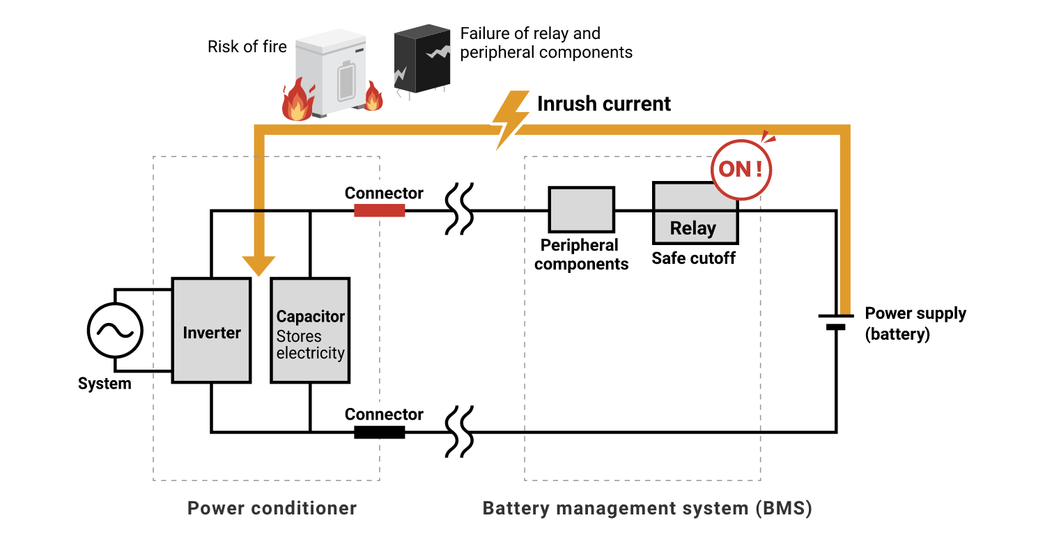
Mechanical relays are widely used for switching power supplies and are mainly used to safely energize and switch high voltages and large currents. If a relay is damaged by excessive electrical load, the electrical circuit will not function properly and may cause a fire, etc. Even if the relay is not damaged, surrounding components such as electrolytic capacitors may be adversely affected by abnormal heat generation of components.
With the recent trend toward higher voltages in devices, inrush current protection circuits are an increasingly important part of electrical circuit design to keep the entire electrical circuit safe. Inrush current prevention circuits also play an important role in stabilizing circuit operation. Inrush current prevention circuits also help to avoid such unstable conditions to ensure stable operation of the circuit.
How the inrush current prevention circuit works
An inrush current prevention circuit is a circuit designed to prevent inrush current from flowing to prevent electronic components, such as relays used to control electrical loads, from being damaged by momentarily large current flow at power-on.
● When power is turned on (until the capacitor is charged with electricity)
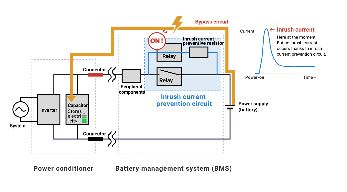
In circuits that need to store electricity in a capacitor, such as an inverter circuit, a large current (rush current) flows immediately after the power is turned on. Therefore, in order to prevent circuit damage caused by this current, a separate current path (bypass circuit) incorporating an inrush current preventive resistor (precharge resistor) is provided so that the current flows into the inrush current preventive resistor until electricity accumulates in the capacitor. This inrush current preventive resistor prevents large currents from flowing, so the relay itself does not need to have inrush current resistance. Depending on the circuit configuration, relays capable of carrying a current of 10 to 20 A are generally used.
● After the capacitor is charged with electricity
When electricity accumulates in the capacitor and the current becomes sufficiently small, the current flow path is switched to the main circuit.
What is a discharge circuit? Why is the discharge circuit necessary?
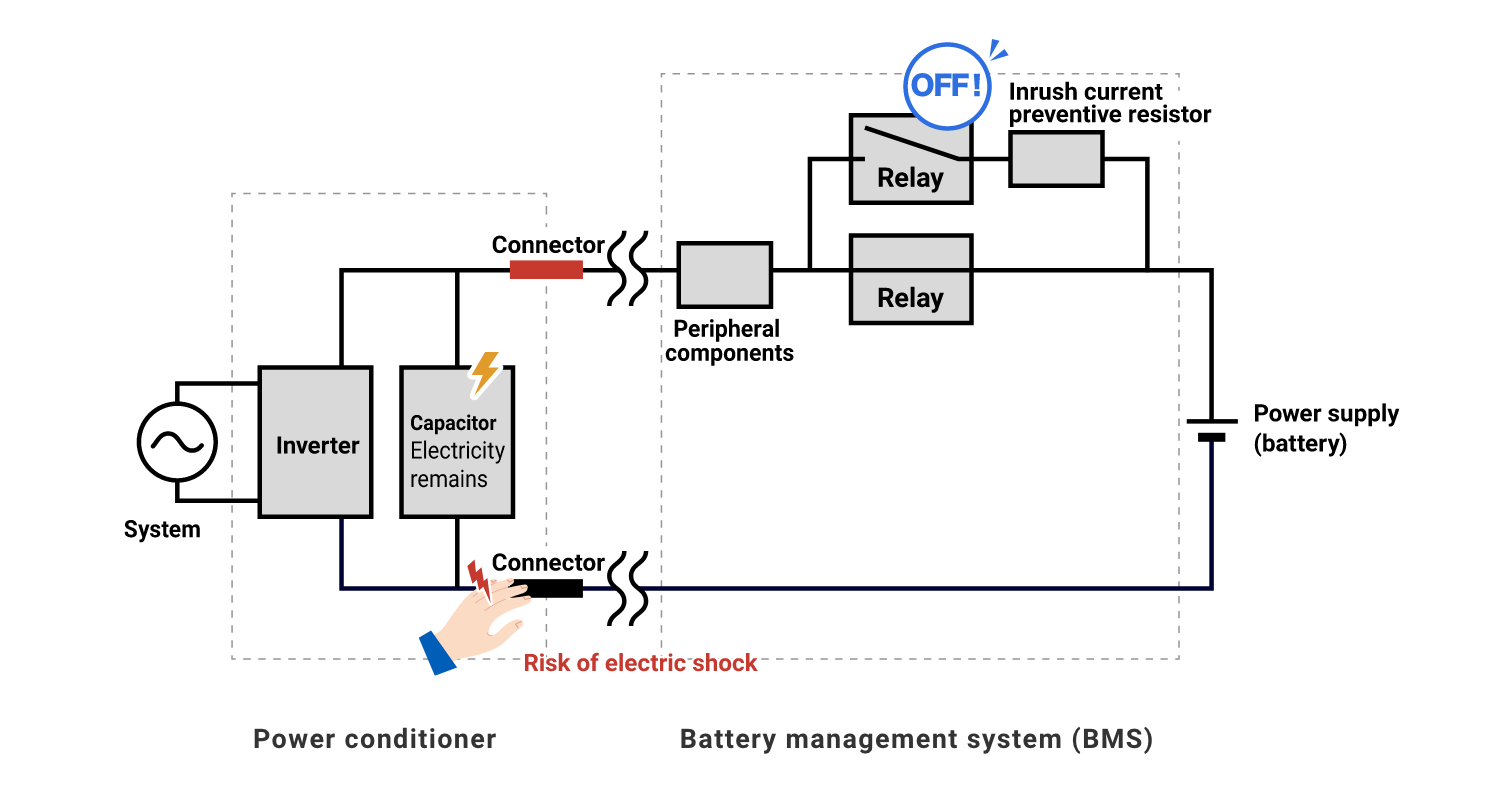
A discharge circuit in an inverter circuit or other circuit is a circuit that discharges the electricity stored in a capacitor.
Electricity remains in the capacitor even after the power is turned off, so touching the connector will result in electric shock.
For energy storage systems, if the discharge time exceeds 1.0 second, it is mandatory to affix a warning label stating the time required for the voltage to drop to a safe level. (JIS C4412-1)
A circuit for discharging electricity in the circuit is essential for safe use.
How the discharge circuit works
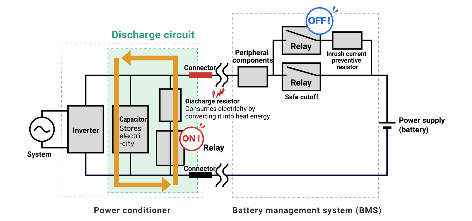
The discharge circuit converts electricity into heat energy and discharges it by passing electricity through the discharge resistor. As with the inrush current prevention circuit, the discharge circuit also incorporates a resistor, so a large current does not flow through the relay.
Which OMRON relays are best suited for inrush current prevention circuits / discharge circuits?
As mentioned above, inrush current prevention circuits incorporate a resistor to prevent the inrush current from flowing, so the relay itself does not need to have inrush current resistance.
For example, the quick charging method using direct current up to 90 kW, which is standardized by the CHAdeMO Association, stipulates that the current flowing through the power line of the charging connector should be 20 A or less when the vehicle contactor is turned on.
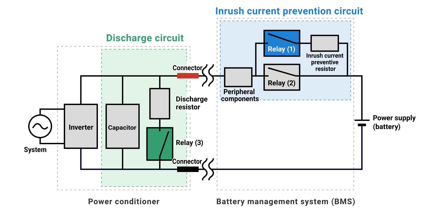
Based on these conditions, OMRON's relay lineup suitable for relays (1) to (3) in the above figure is as follows. How about OMRON's high-capacity relays, which are carefully selected for quality, for highly important circuits where safety is required?
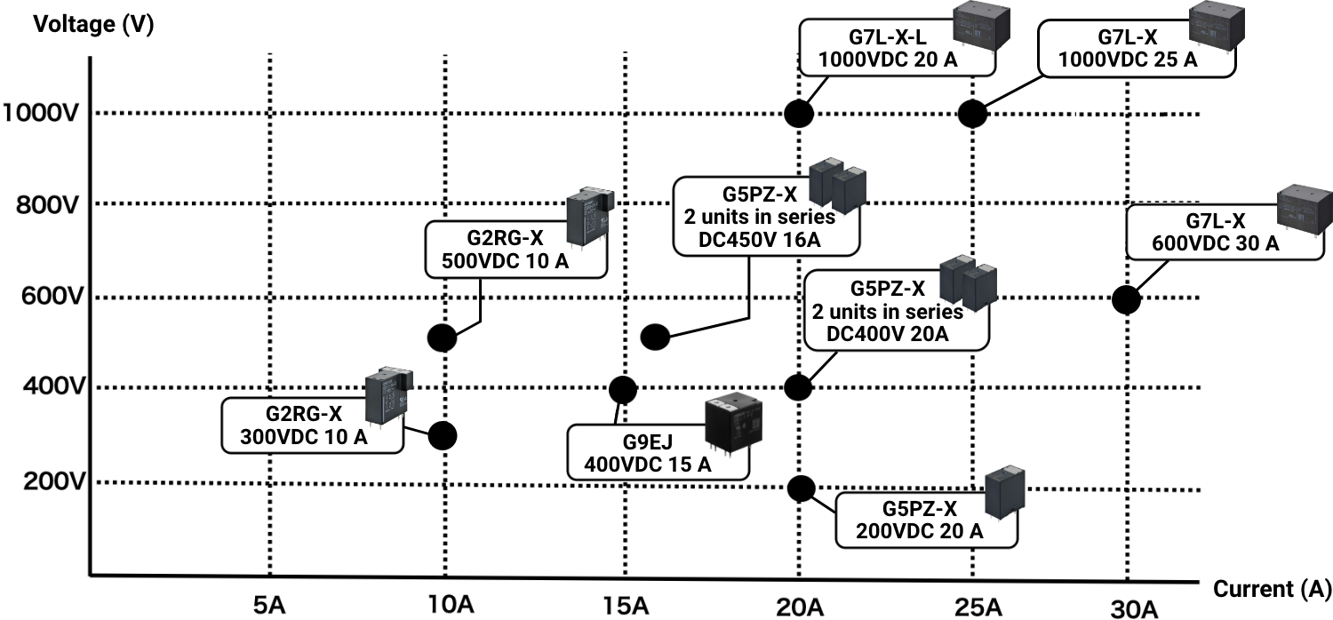
OMRON's high-capacity relay lineup ideal for inrush current prevention circuits / discharge circuits
OMRON offers a wide range of relays to best suit your application.
Easy calculation with formula! Choose the relay best suited for your application
How much current and voltage the relay can withstand depends on how quickly you want the capacitor to complete precharging (charging) after the power is turned on, in other words, how quickly you want the machine to be ready to run. In order to complete precharging quickly, a relay that can withstand a large current is required.
The current value required for the relay to complete the precharge in a specific amount of time can be easily calculated using the following formula.
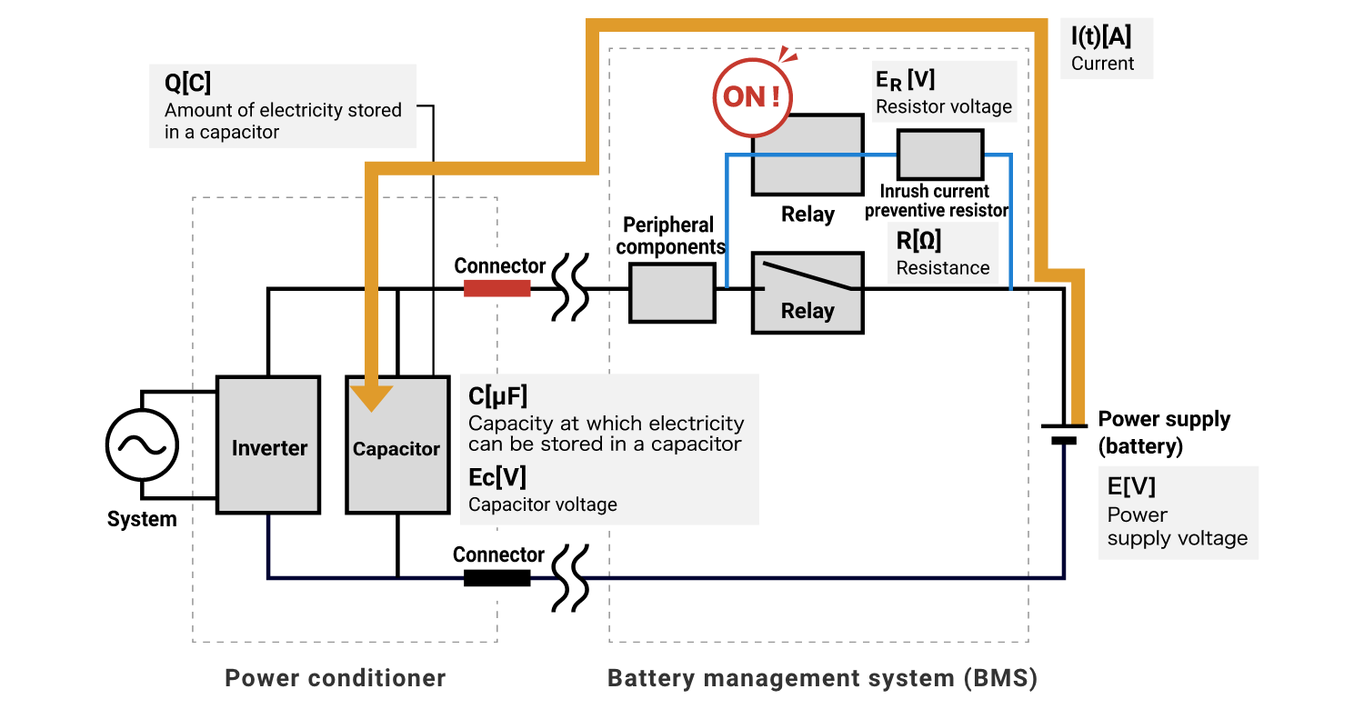
An RC series circuit (a circuit in which a resistor and a capacitor are connected in series) as shown in the figure below is used as an example for explanation.
The amount of electricity Q[C] stored in the capacitor must be zero before the relay is turned on.
As mentioned above, when the power is turned on, a large current is generated as a transient phenomenon (unsteady state) until the capacitor is charged with electricity. As time passes, the current flowing through the circuit decreases and settles to a constant value.
The current I[t] can be calculated using the following formula:

![When t=0 I is E/R. Q[C] Amount of electricity stored in a capacitor. When electricity is fully stored in the capacitor, 'I' is as close to zero as possible.](https://components.omron.com/sites/default/files/2023-09/totsubou_07_03_en.png)
In a circuit with resistors connected in series, the voltage is divided into capacitor and resistor voltages.
E (power supply voltage) = EC+ER
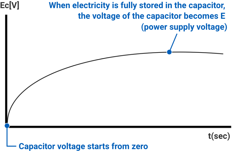
Capacitor voltage EC can be calculated using the following formula:

The voltage across the capacitor starts at zero, and when electricity is stored in the capacitor and the precharge is completed, the voltage becomes power-supply voltage E.
Conversely, the voltage across the resistor starts at the power-supply voltage E, when the capacitor is fully charged, no current flows and the voltage across the resistor becomes zero.
According to the formulas ① and ②, the relationship between the time required for precharging (charging) and the current and voltage of the capacitor is as follows:
| When set as follows: | |
|---|---|
| Capacitor capacity | C[uF]=5000uF |
| Charging resistance | R[Ω]=47Ω |
| Power supply voltage | E[V]=300V |
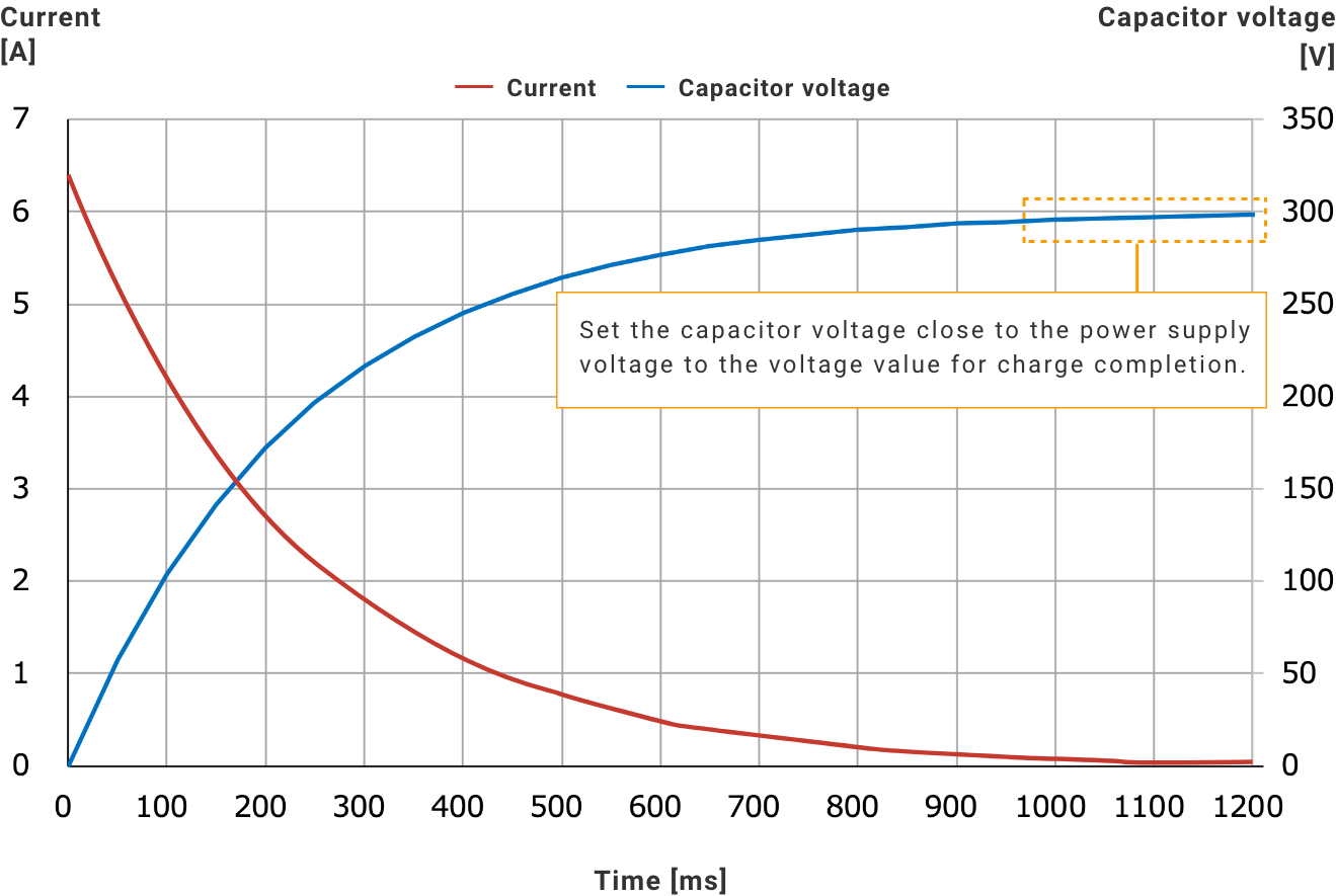
If the capacitor voltage is not as close to the power-supply voltage as possible, a large inrush current will occur. In the circuit conditions shown above, the power-supply voltage is E[V] = 300 V, so the capacitor voltage should be set to a value close to 300 V as the voltage value to complete the precharge.
For example, set the voltage value at the end of charging to 295 V.
If a resistor (R[Ω] = 47 Ω) is chosen so that Ec[V] reaches 295 V in one second, the maximum current I[max] will become 6.4 A according to formula ①.
In other words, if you want to finish the precharge in one second and switch to the main circuit without resistors, you should choose a relay that can energize 10 A.
Please choose the relay best suited for your design.
* 출처
- 오므론전자부품주식회사, https://components.omron.com/kr-en/
문의 사항은 support@samwooeleco.com로 메일 주시면 빠르게 답변 드리도록 하겠습니다.
- 이전글[이벤트 - Murata] KES 2023 23.10.20
- 다음글[Murata Product News] 인덕터(Inductor) - #4 구조 23.10.19