[Murata Articles] PoC system requirements for inductors and noise supp…
- Writer : 최고관리자
- Date : 23-09-18 13:46
- Hit : 784회
본문
1. What is Power over Coax (PoC)?
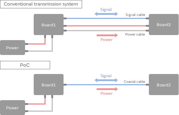
Power over coax, or PoC, is a power transmission method that sends power over signal cables, thereby
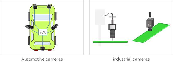
eliminating the need for separate power cables. PoC is used in automobiles and industrial equipment. Automotive
applications for PoC include cameras for ADAS or surround view, where it helps simplify wiring designs and
allows for lighter wiring harnesses. In industrial equipment, PoC applications include cameras for visual
inspections and the like. Large manufacturing lines can require very long cables, and PoC makes it possible
to reduce the number of cables and simplifying cable routing.
How conventional transmission systems and PoC differ
Example applications for PoC systems
2. Circuits required by PoC
PoC is often used for SerDes interfaces, where the serializer and deserializer are connected by a coaxial cable.
High Frequency signal and DC power are superimposed on ths coaxial cable. When this is the case, a Bias-T
circuit is added to prevent high frequency signals from leaking into the power line and DC current from entering
the deserializer. With Bias-T circuits, capacitors that pass high frequency signals while blocking DC current are
used along with coils that pass DC current while blocking high frequency signals.
in this article, the inductors used for Bias-T circuits are referred to as Bias-T inductors.
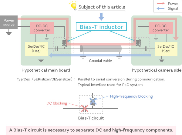 Typical PoC system circuit configuration
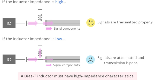
Necessary characteristics of Bias-T inductors
The purpose of a Bias-T inductor is to block AC and allow DC to pass, so the inductor must have high-impedance characteristics. If the impedance is too low, AC signal components may leak into the power line and signal components transmitted over the coaxial cable may be attenuated.
 Bias-T
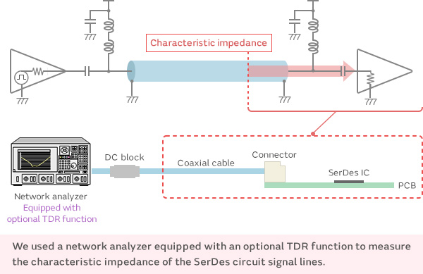
Necessary characteristics of Bias-T inductors Signal line characteristic impedance measurement
We investigated the effect that Bias-T inductors have on the characteristic impedance of the signal line.
We connected a network analyzer to a board populated with components such as a SerDes IC and a Bias-T circuit, and we used the TDR method to measure the characteristic impedance.
 Necessary characteristics of Bias-T inductors Signal line characteristic impedance measurement
Characteristic impedance measurement of signal lines
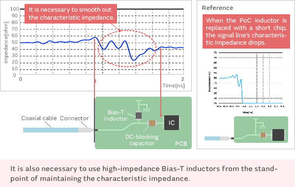
The characteristic impedance of the transmission line varies due to factors such as the pattern design and positioning of components on the board. The transmission characteristics can be improved by suppressing this variation and smoothing it out. To maintain smoothness, the Bias-T inductor must have sufficiently high impedance. This is because the characteristic impedance of the transmission line drops if the impedance of the Bias-T inductor is low. The figure at right shows an extreme example in which the Bias-T inductor is replaced with a short chip. We confirmed that this causes the characteristic impedance to suddenly drop from 50 Ω toward 0 Ω.
 Characteristic impedance measurement of signal lines(source : Murata)