[Murata Articles] Basics of Noise Countermeasures [Lesson 3] Principle…
- Writer : 최고관리자
- Date : 23-09-26 08:04
- Hit : 5,021회
본문
Basics of Noise Countermeasures<Noise filters are low-pass filters>
The previous lesson No. 2 explained that the noise which is an issue for digital devices is mainly caused by the high-frequency (RF) components of digital signals. For this reason, it is understood that low-pass filters, which allow low-frequency signals but not high-frequency signals to pass, can be used to remove this noise.
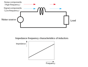
Circuit elements that function as low-pass filters include inductors (coils) and capacitors. As shown in Formula 1, inductors have low impedance (a characteristic like resistance: as the impedance increases it becomes more difficult for signals to pass) with respect to low-frequency components, and high impedance with respect to high-frequency components.
Formula 1 |Z|=2π・f・L (Z: impedance, f: frequency, L: inductance)
Therefore, inserting an inductor in series into the noise path makes it easier for low-frequency signal components to pass, and more difficult for high-frequency noise components to pass.
 Fig. 1 Mechanism by which an inductor functions as a low-pass filter
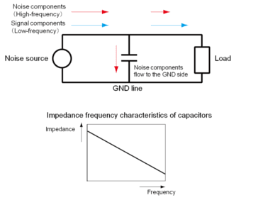
Capacitors, on the other hand, have the opposite characteristics of inductors, and exhibit high impedance with respect to low-frequency components, and low impedance with respect to high-frequency components.
Formula 2 (Z: impedance, f: frequency, C: electrostatic capacity)
To configure a low-pass filter using these characteristics, a capacitor is inserted between the noise path and the GND line. In this case, low-frequency signal components pass as is, but high-frequency noise components escape to the GND side that has lower impedance, so they do not easily pass along the signal path.
 Fig. 2 Mechanism by which a capacitor functions as a low-pass filter
The two types of elements above are the most basic low-pass filters, and higher performance low-pass filters can be configured by combining these elements.
<Number of filter elements and frequency characteristics>
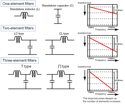
Fig. 3 shows the relationship between the number of elements comprising the filter and the filter frequency characteristics. Insertion loss indicates the degree of signal attenuation due to the filter, and the attenuation amount increases from top to bottom in the figure. The figure shows that the frequency characteristics slope becomes steeper as the number of filter elements increases. Filters with few elements have frequency characteristics with a gentle slope, so they have low selectivity with respect to which frequencies to attenuate and which frequencies to pass. As a result, part of the signal may be attenuated, or noise may not be sufficiently reduced. In contrast, filters with more elements have steeply sloped frequency characteristics, so they exhibit high frequency selectivity and can remove noise without significantly attenuating the signal.
 Fig. 3 Number of filter elements and frequency characteristics
Most EMI suppression filters are created based on this low-pass filter approach, and various techniques are used to increase the noise removal effects.
The next column will introduce typical EMI suppression filters.
person in charge: Murata Manufacturing Co., Ltd. Yasuhiro Mitsuya
The information presented in this article was current as of the date of publication. Please note that it may differ from the latest information.